Maybe it would be fun
To get a new opinion
Get a little work done
And forget
To get a new opinion
Get a little work done
And forget
I was spending a lot of time going up and down stairs working on that bass preamp circuit. I'd build something on my breadboard at my kitchen table or at my desk where there is plenty of light, and then carry it to my son's room to test the circuit with the bass and amp. The problem is, there isn't anywhere as much light in my son's room. So, a lot of times, I'd make a few trips up and down the stairs with my test board until I had something that actually worked. Good for exercise, but for productivity, not so much.
I got to emailing with a friend of mine, as he was starting a low-watt guitar amplifier and speaker cabinet build project. One thing led to another, and I decided it was the right time to build a low-watt practice amplifier. The thought was to have something that I could use in any part of the house for a quick test of a guitar electronics projects before bringing things all the way upstairs for a full test. I had a pre-assembled 1/2 watt LM386 audio amplifier on hand, so most of what I needed to do was to add some speakers and a wooden box. With that, the LeSpork Practice Amp, aka LPA, was born.


It took a couple of iterations to design the
speaker cabinet. It was a balance between common lumber sizes and dimensions that would work with the pair of 4" speakers I had picked out as well as the cabinet aesthetics. Sometime back in high school, I first learned about Fibonacci numbers. As applied to two dimensions, the Golden Rule ratio is 1 : 1.62. For a box, the
ratio of 0.62 : 1 : 1.62 for the sides is considered by some to be ideal. This relationship is what I used for sizing my interior speaker cabinet
dimensions. I started with something wide enough for the two speakers side-by-side, then rounded the height and depth dimensions to the closest standard pre-cut lumber size. Lastly, I worked out dimensions for the cabinet to sit at a slight angle to the floor, so that the speakers would end up pointing slightly upwards, making it easier to hear the sound from this little amp.

The next day, I headed off to the home improvements stores, hoping to find some 3/8 thick dimensional lumber to build a box with roughly 800 enclosed cubic inches and dimensions of 5.75x9.25x15. The closest I found was some plywood and tongue-and-groove wainscot material. I'll take gluing up tongue-and-groove pine boards over cutting plywood any day, so the decision for me was simple.


The next day, I headed off to the home improvements stores, hoping to find some 3/8 thick dimensional lumber to build a box with roughly 800 enclosed cubic inches and dimensions of 5.75x9.25x15. The closest I found was some plywood and tongue-and-groove wainscot material. I'll take gluing up tongue-and-groove pine boards over cutting plywood any day, so the decision for me was simple.

Adding a few pieces of square stock for cleats plus some nails and glue, the sides, top and bottom of the box came together within a few hours over a weekend.
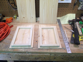


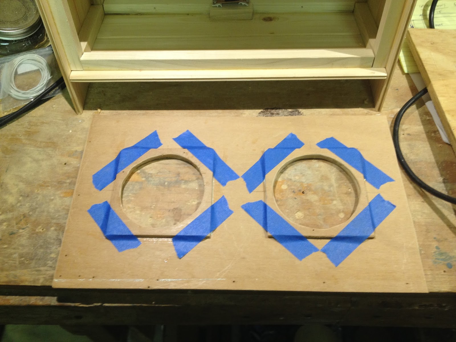
I had a piece of oak veneer panel board on hand and cut a piece out to make the speaker baffle. At only 3/16
thick, it would not support the screws for holding the speakers to it, so I added a pair of mounting "rings" of the same material. They're actually mounting squares, chosen to accommodate the shape of the speaker frames.
I attached the speakers, input jack, amp circuit and a battery clip. After adding some screws to hold the front and back panels on, I plugged in my Tele-esque LeSpork6 prototype guitar for a quick test.


Satisfied that things worked as expected, I built a grille panel from another piece of oak veneer panel board and some jute cloth. It's a nice snug fit and the grille panel can be easily removed with a flat blade screwdriver or similar tool if I ever need to service the speakers.


While waiting for the clear coat to dry on the cabinet, I began focusing on the sound and circuitry. I had built something like this for my son a few years ago, from an old 2-way bookshelf speaker and the same pre-assembled LM386 audio amplifier, and it sounded about the same as this one did. The main problem was the amplifier circuit would distort when the volume control was at or above 3/4 of maximum volume. Second, there was no tone control. For this to be a useful guitar amplifier, I had to address both of these issues while getting as much volume out of it as possible.

The tone control was the simplest of these problems to solve. I already had a Big Muff Pi tone circuit on my breadboard, so I put it in the signal path. between the guitar and amplifier. The addition of this passive circuit between the guitar and amp input jack almost took care of it all, as it cut the incoming signal strength.

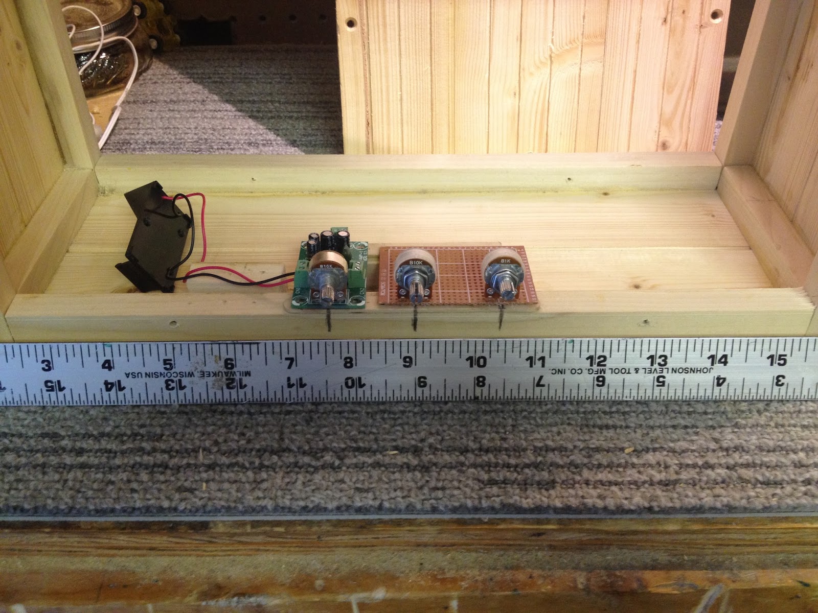
There was just a little bit of distortion with the amp and guitar volume all the way up, but using my son's Epi LP Junior with a humbucker pickup resulted in too much distortion at higher guitar and amp volume settings. What I needed was a preamp stage that would allow me to manage the gain as well as a way to reduce the signal level into the amp enough to keep from clipping the LM386. That also meant the addition of control knobs to the cabinet. That being the easier part of this build for me, I decided on the knob locations and spacing and came up with a way to mount the tone and gain control potentiometers.


Back to the gain and output issues, after some experimentation, I came upon a combination of two simple jfet circuits, an Alembic Stratoblaster Booster and a Fetzer Valve 1.1 Booster.


In order to optimize this circuit for a variety of guitar pickups, I found I could vary the value of Rs=10k, between the J201 transistor Source and ground. I found three particular fixed resistor values that worked well with single-wound pickups, humbucker pickups and active pickup on-board circuits typical in acoustic-electric guitars, that were also compatible with one setting on the 100k trim pot at the preamp output, setting the signal level into the LM386 amp.

The selector switch in the preamp circuit allowed choosing an overall gain range to match the guitar pickup output level, the B100k gain control potentiometer allowed for a gain adjustment that includes a tube-like overdriven effect at the upper range of the control, and the 100k trim pot kept the preamp output low enough to avoid clipping distortion in the LM386 amp.

I found a few things to maximize the volume of this little 1/2 watt power amplifier in the schematic notes and technical data for my power amp. The notes indicated removing the on-board jumper would provide additional gain. The datasheet also indicated this, and included instructions on adding a resistor at the jumper contacts would produce different levels of gain. Unfortunately, taking off the jumper resulted in a large loss of volume as well as large reductions in the overdriven ranges. Trying a 1k pot in place of the amp jumper also resulted in lower volume levels as well as reductions in overdriven ranges. Switching the gain control from a B100k pot to a B50k, as drawn in the Alembic Stratoblaster circuit, provided a smoother set of gain ranges, but did nothing to allow for any more volume. Seeing no other ways to optimize this circuit, I decided to set it aside for now and try some other preamp circuits with this 1/2 watt amp and speaker setup.


Since jfet preamp circuits typically have a warm tone than their NPN and PNP counterparts, I thought there might be a way to use a jfet stage to take the edge off of the LPB-1. Feeding the output of a Fetzer Valve stage through a trim pot into the LPB-1 yielded some nice tone, so I replaced the first stage trim pot with a B100k potentiometer. After turning through a rather large clean range, the upper range of this control allowed the first stage to overdrive the second stage. Turning up the drive control all the way allowed for using the guitar volume as a gain control with a very small clean range, as well as a HUGE amount of sustain with the upper end of the guitar volume control. But, this came at the cost of some muddiness in the harmonics that detracted from the overdriven sound.

Finally, I swapped the two preamp stages, putting the LPB-1 in front of the Fetzer Valve with the B100k drive control in the middle. Knowing the gain of the NPN stage could easily overdrive the jfet stage, I was pleased at how well this combination worked. With two stages of amplification in this preamp, I expected to have to keep the Fetzer Valve trim output very low to keep from overdriving the amp, and was pleased to find the power amp could handle the preamp output up to about half of its 100k range with a single pickup guitar. I also found a good amount of usable Drive control settings that produced clean sounds when turning the guitar volume control down. This left plenty of knob rotation on both the Drive control and guitar volume control for inducing a wide range of tasty jfet overdrive, all the way from mild after-buzz to all-out, long-sustaining, mega buzzing sounds, full of rich harmonics. To my surprise, the humbucker on my son's LP Junior did not significantly alter the Drive control ranges or require me to reduce the output level into the amp. This circuit even worked with the preamps on my acoustic-electrics. Considering how versatile this setup was with just the three controls and without the need for a gain range selector switch, I settled on this preamp circuit for the LeSpork Practice Amp. All that was left then was to solder the rest of the circuit to the board, bias the J201 transistor, reassemble the amp, add some insulation to the inside of the cabinet, and reattach the rear cabinet panel.


Time to stick a Spork in this project and call it done, and play some of These Old Guitars!


Satisfied that things worked as expected, I built a grille panel from another piece of oak veneer panel board and some jute cloth. It's a nice snug fit and the grille panel can be easily removed with a flat blade screwdriver or similar tool if I ever need to service the speakers.


While waiting for the clear coat to dry on the cabinet, I began focusing on the sound and circuitry. I had built something like this for my son a few years ago, from an old 2-way bookshelf speaker and the same pre-assembled LM386 audio amplifier, and it sounded about the same as this one did. The main problem was the amplifier circuit would distort when the volume control was at or above 3/4 of maximum volume. Second, there was no tone control. For this to be a useful guitar amplifier, I had to address both of these issues while getting as much volume out of it as possible.

The tone control was the simplest of these problems to solve. I already had a Big Muff Pi tone circuit on my breadboard, so I put it in the signal path. between the guitar and amplifier. The addition of this passive circuit between the guitar and amp input jack almost took care of it all, as it cut the incoming signal strength.

There was just a little bit of distortion with the amp and guitar volume all the way up, but using my son's Epi LP Junior with a humbucker pickup resulted in too much distortion at higher guitar and amp volume settings. What I needed was a preamp stage that would allow me to manage the gain as well as a way to reduce the signal level into the amp enough to keep from clipping the LM386. That also meant the addition of control knobs to the cabinet. That being the easier part of this build for me, I decided on the knob locations and spacing and came up with a way to mount the tone and gain control potentiometers.


Back to the gain and output issues, after some experimentation, I came upon a combination of two simple jfet circuits, an Alembic Stratoblaster Booster and a Fetzer Valve 1.1 Booster.


In order to optimize this circuit for a variety of guitar pickups, I found I could vary the value of Rs=10k, between the J201 transistor Source and ground. I found three particular fixed resistor values that worked well with single-wound pickups, humbucker pickups and active pickup on-board circuits typical in acoustic-electric guitars, that were also compatible with one setting on the 100k trim pot at the preamp output, setting the signal level into the LM386 amp.

The selector switch in the preamp circuit allowed choosing an overall gain range to match the guitar pickup output level, the B100k gain control potentiometer allowed for a gain adjustment that includes a tube-like overdriven effect at the upper range of the control, and the 100k trim pot kept the preamp output low enough to avoid clipping distortion in the LM386 amp.

I found a few things to maximize the volume of this little 1/2 watt power amplifier in the schematic notes and technical data for my power amp. The notes indicated removing the on-board jumper would provide additional gain. The datasheet also indicated this, and included instructions on adding a resistor at the jumper contacts would produce different levels of gain. Unfortunately, taking off the jumper resulted in a large loss of volume as well as large reductions in the overdriven ranges. Trying a 1k pot in place of the amp jumper also resulted in lower volume levels as well as reductions in overdriven ranges. Switching the gain control from a B100k pot to a B50k, as drawn in the Alembic Stratoblaster circuit, provided a smoother set of gain ranges, but did nothing to allow for any more volume. Seeing no other ways to optimize this circuit, I decided to set it aside for now and try some other preamp circuits with this 1/2 watt amp and speaker setup.

First up was the well-known LPB-1. As I knew from another project, the
LPB-1 has a lot more gain and a much brighter tone than the Fetzer Valve
circuit. I used a 2N5089 transistor, and instead of using the 830k/100k resistors shown here, I biased the transistor base with a 470k/47k voltage
divider. It rocked the
socks off of the LPA but with too much gain for my taste, overdriving the LM386 amp except at a very low output level that was not loud enough to be useful in a clean mode.

Following a mod I found in a chat
room, I added a a gain control made up of a 22uF cap and a B5k pot in series, parallel to
the
330R emitter resistor, similar in configuration to the
StratoBlaster circuit. The gain control allowed for good clean and overdriven ranges, but had a noticeable surge in the
higher end of the overdriven range. This was easily
fixed by swapping out the B5k to a B1k pot, resulting in a smaller but very usable clean gain range. Although this circuit worked well, it was a
bit too bright with this setup for my tastes. Besides that, the inherent noise of the NPN transistor in this circuit was enough to make me continue searching for another circuit.

Since jfet preamp circuits typically have a warm tone than their NPN and PNP counterparts, I thought there might be a way to use a jfet stage to take the edge off of the LPB-1. Feeding the output of a Fetzer Valve stage through a trim pot into the LPB-1 yielded some nice tone, so I replaced the first stage trim pot with a B100k potentiometer. After turning through a rather large clean range, the upper range of this control allowed the first stage to overdrive the second stage. Turning up the drive control all the way allowed for using the guitar volume as a gain control with a very small clean range, as well as a HUGE amount of sustain with the upper end of the guitar volume control. But, this came at the cost of some muddiness in the harmonics that detracted from the overdriven sound.

Finally, I swapped the two preamp stages, putting the LPB-1 in front of the Fetzer Valve with the B100k drive control in the middle. Knowing the gain of the NPN stage could easily overdrive the jfet stage, I was pleased at how well this combination worked. With two stages of amplification in this preamp, I expected to have to keep the Fetzer Valve trim output very low to keep from overdriving the amp, and was pleased to find the power amp could handle the preamp output up to about half of its 100k range with a single pickup guitar. I also found a good amount of usable Drive control settings that produced clean sounds when turning the guitar volume control down. This left plenty of knob rotation on both the Drive control and guitar volume control for inducing a wide range of tasty jfet overdrive, all the way from mild after-buzz to all-out, long-sustaining, mega buzzing sounds, full of rich harmonics. To my surprise, the humbucker on my son's LP Junior did not significantly alter the Drive control ranges or require me to reduce the output level into the amp. This circuit even worked with the preamps on my acoustic-electrics. Considering how versatile this setup was with just the three controls and without the need for a gain range selector switch, I settled on this preamp circuit for the LeSpork Practice Amp. All that was left then was to solder the rest of the circuit to the board, bias the J201 transistor, reassemble the amp, add some insulation to the inside of the cabinet, and reattach the rear cabinet panel.


Time to stick a Spork in this project and call it done, and play some of These Old Guitars!
nice info
ReplyDeletenice info
ReplyDelete