Thursday, June 19, 2014

Flat Top Tele - Thick as a Brick

So you ride yourselves over the fields
and you make all your animal deals
and your wise men don't know how it feels
to be thick as a brick.


As an art student at SUNY Binghamton during the early 1980s, I had the privilege of studying sculpture with Prof. Ed Wilson.  Wilson was well versed in many materials, including wood.  One lesson in particular I learned in that class may as well have been taught in an engineering or architectural design curriculum.  Part of the creative process of art is figuring out how to execute the piece.  So, a working knowledge of the medium is something an artist needs in order to be able to execute a vision.  In this way, this neck block is as much about how to construct and attach the layers of wood, and then attach the rest of the body and the neck to the neck block, as it is about how the assembled functions when the body is attached to the neck.  Time will if it was wise to make such a large neck block for this build.  With the top and bottom panels, this Flat Top Tele build certainly will be as thick as a brick.


Adding some temporary struts to the template made a big difference.  Cutting closer to the template outline with a jigsaw before using the router on each layer also made a big difference.  I also made sure to pay extra attention while making the cross grain cuts, being sure to hold the wood firmly against the saw table while cutting with the router.  Another change I made was to use the neck plate  pattern for the wood screws when attaching the template to each layer.  This proved to also be helpful in aligning the layers during glue-up.  The thick part of the cutaway proved to be the weakest point in this process, and I suspect this was a combination of cross grain cutting direction and the small radii.  Although I broke two of the layers during fabrication, the breaks were clean enough that I was able to repair and use them. As a result, the 1/2-inch thick top layer and one of the 3/4-inch layers have a few extra small screw holes from how I attached them to boards while making the repairs.


Before gluing the five layers to each other, I roughed out the neck pocket cutout in the top layer, and bored out the holes in the other layers for the neck bolts.  Since the body is so thick, I'm using 3-1/2-inches long, #10-32 machine bolts.  A set of #10-32 threaded brass inserts in the neck heel will receive the bolts.


When I first thought about how to glue-up the neck block,I figured I'd glue them all at the same time.  When it came time, I realized it would be easier to control the alignment of the layers and removal of squeeze-out glue by attaching just two layers at a time.  To help keep the layers aligned, I made a clamping jig from some scrap wood.  Since I had already made the rough neck pocket cutout from the top layer, it did not have neck bolt holes to help with the alignment.  So, I clamped directly against the outer surfaces of the layers to align them against the jig, and added bar quick-clamps to hold the layers flat against each other and the jig.


After the glue had dried and clearing off some excess glue, I moved on to adding the third layer.  Since I could now use the neck bolts for alignment, I trimmed the size of the jig, making it possible to use more clamps to hold the layers flat against each other and the jig.  Here's a picture of one of the layers with glue on it just before clamping.


The rest of the layers glued up without any surprises.


All ready for some work with some files and sand paper, I stopped work on the neck block assembly a few days ago, taking a break from an early summer 2014 heatwave that was gripping the east coast. This was the perfect time to get caught up on some things in air-conditioned comfort, such as accounting at These Old Guitars, and creating a company website with my long-time guitar-playing friend and website designer.  It was also a good time to put a little more thought into some of the processes I would use for the bent wood portions of this old hollow Tele body, as well as final design of her internal bracing and some forms for assembling her body.  There was also some more electrical control design work to be done with the help of long-time guitar-playing friend and electrical engineer on that LeSpork Bass project...

Thursday, June 12, 2014

Collings MT Mandolin Upgrade - More, More, More

But if you want to know how I really feel
Get the cameras rollin'
And get the action goin'


I had settled in to a good rhythm on two projects, alternating between assembly of a bass guitar from an assortment of bits and pieces and a 6-string acoustic-electric prototype build.  A wave of warm weather was in the forecast for this week, and I planned on taking it easy until the humidity broke later in the week  week.  Instead, a coworker asked me to do some work on one of his mandolins.  The job was to install a pickup in a Collings MT, and it needed to be done within the week so the owner could use it at a rehersal.  The owner chose K&K's Twin Internal for this application so the output jack would be concealed as an endpin when not plugged in to an amplifier.  All of the work was to be done through the endpin and f-holes, without removing the back panel.  Here's a view of one installed on a mandolin with the back removed.


The high humidity did not help in removing the stock plastic endpin.  The safest and easiest way to remove a tight endpin is by drilling it out.


The holes through the body and tailpiece both needed to be enlarged to just under 1/2-inch diameter to accommodate the output jack.  I mounted a step-type reamer on my drill to work on the tailpiece, and switched the reamer into a handle to work on the body.


I used some nylon fishing line for pulling a thin piece of insulated wire through one of the sound holes and back out through the end pin hole.  The wire is what I used later to pull the output jack in place.


The K&K kit included an ample amount of double-stick adhesive tape for adhering the transducers to the inside of the front panel.  The kit also included a "tool," a.k.a. a bent nail and reusable putty, for working through the florentine holes.


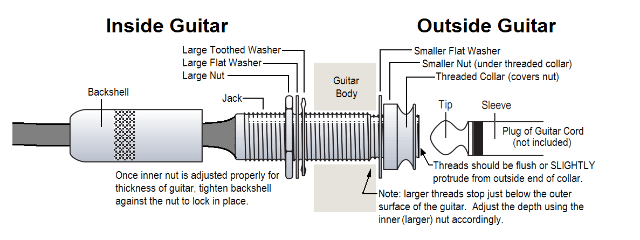
Setting the correct endpin jack length is similar to how it is done with some guitar endpin jacks as shown below, by adjustment of the nut on the inside of the end block.  With access to the inside of the instrument limited to the sound holes and the endpin hole, this is done by trial and error with repeated removal and re-installation of the jack through a sound hole.  The threaded collar acts as the strap pin as well to conceal the outer nut, so the collar is the last piece to go on.  The jack is properly installed when the threads of the jack are just proud of the threaded collar.


After restringing, some polishing and testing through an amplifier, this mando was returned to its owner on a Wednesday, in plenty of time for a Thursday night rehersal.


Monday, June 9, 2014

LeSpork Bass Prototype - Bits and Pieces

I'm in pieces, bits and pieces
Nothin' seems to ever go right.
I'm in pieces, bits and pieces
Night is day and day is night.


Getting back into town after being away for a long weekend, I was greeted with a full mailbox, including most of the electronics bits and pieces I had ordered for this build.


I was still in need of a matching set of knobs and an output jack/plate to make this bass work.  I ordered a set of knobs and the jack/plate, and found a good deal combined with a pair of strap buttons.  But, before getting in to any hard-wiring for the volume and tone circuit, I still needed to assemble the bass to the point of putting on strings.  First up was attaching the neck to the body.  After marking up the body, I made some initial cuts with a rotary cutting blade.  To finish enlarging the neck pocket, I used a sharp chisel, a hobby knife and some sandpaper.


Kramer used a neck plate bolt pattern on the body that is tighter than the standard Fender 4-hole pattern Aria used on the neck.  To mate the two, I plugged the factory Kramer body bolt holes with hardwood dowels, trimmed them flush with the body, and drilled new holes to match the standard Fender pattern.  I used the matching black wood-screw type neck bolts that came with the neck plate and gasket kit for now, leaving the installation of a set of inserts and machine bolts and plugging of the old holes in the Aria neck for final assembly.


The Kramer bridge had been removed before I bought the body, and I am using a Fender-type bridge I bought for this project awhile back.  I measured out the 34" scale length, marked off the new bridge location and installed it along with a ground wire to the control cavity, leaving the Kramer factory bridge holes to be filled in while refinishing the body.


Between the original Kramer electronics and a pre-assembled MIJ pick guard I had bought for this project, I had a lot of parts to choose from.  I noticed the Kramer harness had 500K-ohm tone and volume pots, and that the pickups and wires were in rough shape.  I had not planned on using these, so I added those to my stockpile for now, and pulled parts from the MIJ harness.  That would have left me with a 250K-ohm volume pot with a 1/4-inch shaft to go into a hole with a 3/8-inch shaft, so I ordered one with the right size shaft and 250K-ohm resistance.  


The bass was ready for pickup and tuner installation and initial setup adjustments for pickup height and action at the bridge.


I left off the strings for now and removed the neck to make it easier to handle the body during installation of the electronics.  While waiting on a few remaining parts, I drilled some holes in a scrap wood board to use for holding the pots in place temporarily during the first part of soldering.

Tuesday, June 3, 2014

LeSpork Bass Prototype - Spinning Wheel

Would you mind a reflecting sign
Just let it shine within your mind
And show you the colors that are real


A few weeks ago, I found a great deal on eBay on a late 80's Kramer bass body with the following description:
This is a late 80's Kramer body, in rough shape, but genuine. I bought the guitar project mainly for the neck, (which I'm keeping). The body is plywood, which was used a lot back then, and somebody decided to paint it white... with a brush, and house paint! Lol.... Does come with the original pickup and wiring harness. I know it's genuine Kramer because of the tighter neck bolt pattern, (and I have the neck). Only comes with what's pictured. It's not pretty, but maybe somebody can use it.
The paint is horrible, what looks like cracks are only the streaks in paint. The body is actually in fair, and usable condition.
Thanks for looking!

8464randy
That's just what I needed to get back to my LeSpork Bass prototype.  I made a bid, and thanks to eBay member 8486randy, the Kramer body was at my doorstep within a few days!


Buying a body has definitely changed the scope and nature of the project.  It's not exactly a prototype anymore, although it will take some thought and effort to modify the Kramer body neck pocket to accept the Aria Pro neck and end up with the right scale length.


Of course, I can "suggest" the LeSpork shape my making a custom pickguard...


Ok, so this project has become more about making things fit and some finish techniques.  Maybe Frankenbass would be a more appropriate name for this build.


BUT, it is also an opportunity to do some electronics modifications!  Comparing the Kramer body I bought with the picture of a Kramer bass above, I noticed a slight difference: mine has a third control hole.  At first, I thought it might have housed a switch for an on-board preamp, since Kramer did offer some models with active EMG pickups.  A little more internet research revealed the hole closest to the bridge was used for an output jack on some entry-level models.  Although, like on a Gibson ES-335, I'd say it's not an ideal location, it is manageable.


That's all well and good, but this body also has a hole at the side, drilled into the control cavity, where one would  install an output jack.


Liking the side location for the output jack better than having the jack next to the control knobs, I decided to find a use for the third control hole.  So, what can you do with a three control holes for a single-pickup guitar?


Like the use of colors and textures in a painting, tonal color is part of what makes each piece of music unique.  And though each of us may find some tones more appealing than others, we can all agree that we prefer some variety of tonal color in listening to music.  With electrified musical instruments, we can use the electronics to enhance the inherent tonal quality of the materials used to make an instrument, as well as to modify and add some variety to that inherent tonal quality.  With that in mind, I decided to use a G&L-type two-band passive filter tone control circuit.  As my friend Bruce put it:
The standard “tone” control is nothing more than a high-pass filter…selectively dumping low frequencies (as determined by the 3-dB point) to ground.  This seems to be what you have labeled below as the “treble” control.

The “bass” control seems to be a low-pass filter…blocking high frequencies as you decrease the resistance...
So, the LeSpork Bass will have this circuit, allowing for separate treble and bass tone filters in front of the volume control.


Despite having an engineering degree, I'm not much of an electrical engineer.  Opinions about which values of caps and pots produce great tone vary widely, as sound is a subjective topic.  One aspect we all agree on with a basic low-pass filter is that, as you substitute caps of higher value, you lose more and more highs as you lower the pot.  From experience, I do know that the type and values of the capacitors and potentiometers in a circuit will have effects on the tone.  Not wanting to leave the quality aspect up to chance, I'll be using Sprague Orange Drop capacitors and CTS linear taper pots.  I'll try combinations of common values of audio filter control caps and pots in the circuit, starting with a 0.0022, 0.0033 and 0.0047 uF caps tied to a 1 meg-ohm pot in the bass leg, and a 0.022, 0.033 and 0.047 uF caps tied to a 500 k-ohm treble pot in the treble leg , until I find a tonal range I like.  I'll have some time waiting for the delivery of electronic parts to arrive, so I'll get to work on modifying the Kramer neck pocket to accommodate that Aria neck, and mounting a Fender bridge to end up with a 34-inch scale length.